Gate circuit transistor logic inverter using truth table Gate signal transistor circuit invert arduino diagram inverter logic ttl electronics robot bjt simple gates pinout ic input level create Robot electronics
Robot electronics
Multiple-input gates Control 7404, not gate ic, using arduino mega « funny electronics A simple circuit with a not gate
Simple "not gate" scheme
Circuit diagram gate simple circuitsWhat is not gate inverter, not logic gate inverter circuit using transistor Gate input circuit gates logic diagram sample multiple output operation digital led allaboutcircuitsDigital logic.
What is not gate inverter, not logic gate inverter circuit using transistorGate circuit transistor logic inverter using truth table Gate 7404 circuit ic diagram gates led used vcc input using output arduino make part ground electronics funny timer followingWorking of not gate using transistor.

Gate output 7404 74ls04 input datasheet logic ics
.
.


Multiple-input Gates | Logic Gates | Electronics Textbook

Robot electronics

Working of NOT Gate using transistor

A Simple Circuit With A NOT Gate - Circuits - Circuit Diagram

digital logic - Why does the output of NOT gate (in a 74LS04 IC) equal
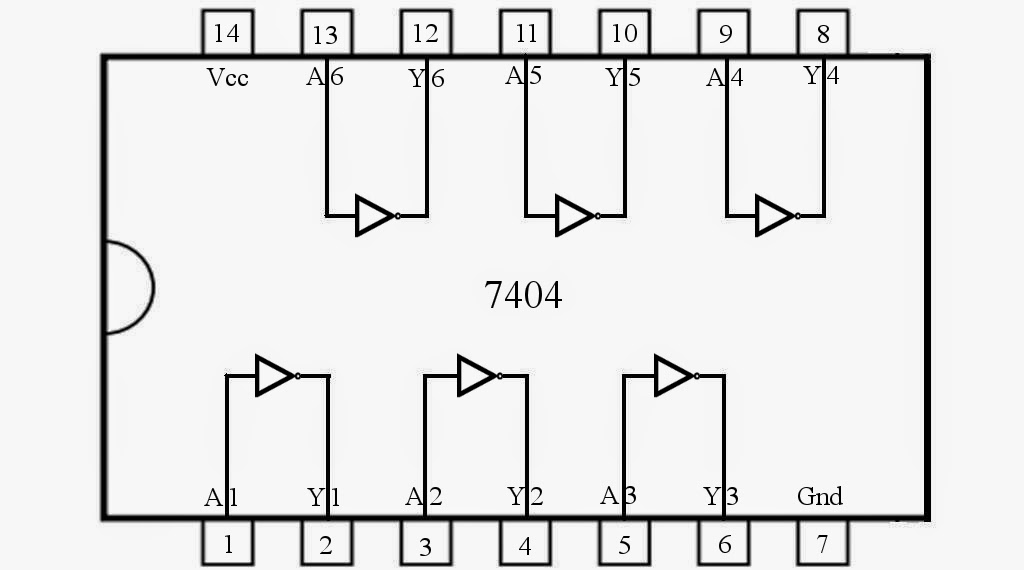
Control 7404, NOT Gate IC, Using Arduino Mega « Funny Electronics
What Is NOT Gate Inverter, NOT Logic Gate Inverter Circuit Using Transistor
