3-phase pwm inverter Three-level single phase inverter circuit Three-phase pwm inverters with a r-l load.
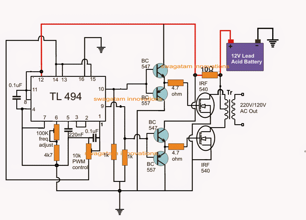
IC TL494 PWM Modified Sine Wave Inverter Circuit
Inverter pwm tl494 circuit ic sine wave modified pinout functions executing above looking many Ic tl494 pwm modified sine wave inverter circuit Principles of operation
Phase pwm inverter
Pwm three invertersVfd diagram ac drives wiring operation motor principles panel circuit variable frequency drive schematic dc pulse width inverter phase vsd .
.

Principles of Operation - AC VFD Drives

IC TL494 PWM Modified Sine Wave Inverter Circuit

Three-level single phase inverter circuit | Download Scientific Diagram

3-phase PWM inverter - Electrical Engineering Stack Exchange